Funded by the Horizon Europe Programme of the European Union under grant agreement No 101096809
Funded by the Swiss State Secretariat for Education, Research and Innovation
Introduction
This fact sheet offers insight into various applications of fuel
cells for propulsion and auxiliary power in inland ships.
Hydrogen storage options and alternative energy carriers are
presented with their pros and cons in brief. Information ranges
from relevant regulations, technical concepts including benefits
and downsides to recommendations for further reading.
Facts
Fuel cells are energy converters that continuously convert the
chemical energy of the fuel, such as hydrogen, natural gas or
methanol, into electrical energy and thermal energy (heat losses)
using an oxidant such as oxygen. The fuel cell can supply electricity
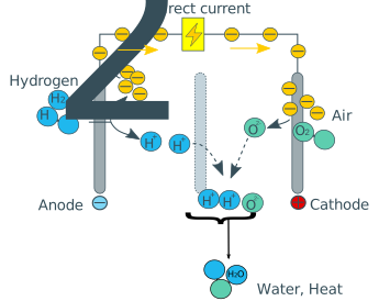
as long as suitable fuel is available. The basic working principle
can be seen in .
The principle of the fuel cell was invented in 1838, however the first
commercial use of fuel cells came
more than a century later in NASA space programs to generate power for
satellites and space capsules. Since then, the improvement of the fuel
cell began and nowadays they are used in many other applications, e. g.
for primary and backup power for commercial, industrial and
residential buildings and in remote or inaccessible areas. The second
most important application for fuel cells is as a power source for
vehicles of all kinds.
Basic working principle of a PEM fuel cell.
With fuel cells local emission-free
power generation is possible. The comparison of a fuel cell with a
conventional internal combustion engine shows that no mechanical stress
on components takes place because no fuel is burned. This results in no
wear, vibration, or generation of noise.
Emissions
When talking about emissions, there are initially
different ways of looking at them: On the one hand, a distinction is
made between toxic and climate-impacting emissions. On the other hand, a
distinction is made between local and global emissions. Examples of
toxic emissions are nitrogen oxides, particulates, formaldehyde, etc.,
while climate-impacting emissions include CO2, methane, laughing gas,
etc. Local emissions have effects on the immediate surroundings of the
source, such as toxicity. The effects of global emissions are not
limited locally; they can be climate-impacting substances, for example,
or the now banned CFC, which damages the ozone layer or sulphur
emissions from the seagoing sector.
If the emissions caused by a propulsion
technology or an energy source are to be assessed, there are again
various approaches. The most common are the well-to-wake and the
tank-to-wake approach. In the well-to-wake approach, the emissions from
the entire upstream chain required for the production and supply of an
energy carrier are considered. For an engine, a fuel cell or a battery
this approach is called Life-Cycle-Analysis. The tank-to-wake approach
looks at the emissions generated by the ship during use. Everything that
happened before the energy carrier, storage system or energy converter
came on board is excluded. These two definitions can produce very
different results in the assessment of the technologies. For example,
when considering the overall chain, the choice of a methanol combustion
engine could be better than that of a battery-electric drive. This is
the case if the production of the battery causes more emissions than the
combustion of methanol. It is important to note that this type of
consideration is also different for each ship and depends on its
operating time and energy requirements. The following table shows the
relevant emissions for this fact sheet.
Emission compared to conventional diesel
Local
Global
GHG
The global GHG emissions are dependent on the hydrogen source.
NOX
better
SOX
PM
Regulations
The technical
requirements for fuel cells are included in ES-TRIN 2023, Chapter 30,
Annex 8, Section 3.1. The technical requirements for the storage of
hydrogen are foreseen in ES-TRIN 2027 Chapter 30, Annex 8, Sections 2.3
and 3.4.
For seagoing vessels, the
IMO circular 1647 from 15 June 2022 (Interim guidelines for the safety
of ships using fuel cell power) applies.
Technical Concept
Basic Working Principle of Fuel Cells
All fuel cells consist of two electrodes -
the anode and the cathode. These are separated by an electrolyte with an
ion-permeable membrane. After the fuel has been supplied to the anode,
it is divided into electrons and protons. The free electrons flow into
an outer circuit between the anode and cathode to be used as an electric
current. The protons spread through the electrolyte to the cathode. At
the cathode, the oxygen from the air combines with the electrons from
the outer circuit and protons from the electrolyte. This results in
water and heat.
Several fuel cells in a row make up a
fuel cell stack. The number of individual cells that are connected in
series can be used to variegate the performance of the stack and adapt
it to the respective requirements.
All fuel cell types are based on the
reaction of a fuel with oxygen. The electrochemical reaction generates
basically electricity, heat and water. From the fuel cell, the
electricity is provided as direct current (DC). If alternating current
(AC) is required for further use, DC from the fuel cell is routed to an
inverter is converted there to AC.
Classification of Fuel Cells
Basically, fuel cells are classified
according to their operating temperature and the type of electrolyte
used in the fuel cell. The following fuel cells are particularly
interesting for inland waterway vessels:
Low Temperature Proton Exchange Membrane Fuel Cell (LT-PEMFC)
PEMFC uses a water-based polymer membrane as electrolyte, H2 as
fuel and O2 as oxidant. The operating temperature
is < 100 °C. Due
to the low temperature, only pure hydrogen can be used in PEMFC. The
byproducts besides electricity are water and heat. The fuel cell can be
started cold without pre-heating to the operating temperature.
High Temperature Proton Exchange Membrane Fuel Cell (HT-PEMFC)
If the operating temperature is
significantly exceeding than 100 °C, PEMFC is used. These can reach up to
200 °C and used mineral acid electrolyte instead of a water based one.
The fuel cell must first be brought to operating temperature before it
functions properly.
Solid Oxid Fuel Cell (SOFC)
SOFC contains a solid electrolyte. From
an operating temperature of approx. 650 °C, this so-called oxide ceramic
conducts the hydrogen ions through it. Some devices reach a temperature
of 1,000 °C. SOFC is one of the high-temperature fuel cells. An internal
reforming of natural gas to hydrogen takes place in SOFC itself.
Propulsion Concept
Components on Board
The fuel cell system as a propulsion
system for a ship often consists of several components. These include
the fuel cell, an electric motor, accumulators and partly a reformer. A
negative property of the fuel cell is its own inertia to react. This
inertia is balanced by an accumulator. It must also be taken into
account that a fuel cell needs some time to reach operating temperature,
this time difference is also compensated by the accumulator. The fuel
cell supplies direct current, the energy produced is transmitted to an
electric motor for propulsion. This electric motor, for example,
generates the rotary motion for the propeller shaft. The energy
requirements for all electrical equipment on board a ship can be
supplied directly from the fuel cell or accumulator without detours.
The arrangement of the fuel cell
and the accumulator can be either parallel or in series. The following
diagram shows the basic conversion process in a fuel cell using the
example of hydrogen as a fuel.
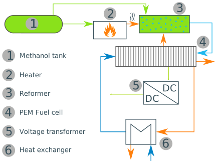
Methanol System for a HT-PEMFC
From the methanol tank (1) the
fuel is taken to the reformer unit (3) to extract the hydrogen from it.
The process needs heat which is produced by burning an amount of
methanol in the heater (2).
The pure hydrogen is then fed into
the fuel cell (4). Some of the reaction heat in the fuel cell is fed
back in the reformer. The remaining heat is emitted in a separate heat
exchanger system (6).
The voltage of the electric current produced is transformed into the
usual on-board voltage by the voltage transformer (5).
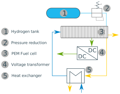
Hydrogen System for a HT-PEMFC
The hydrogen’s high pressure in
the tank (1) is lowered to a for the fuel cell suitable amount in the
pressure reduction unit (2). From there it is fed into the fuel cell.
The voltage of the electric current produced is transformed into the
usual on-board voltage by the voltage transformer (4).
The reaction heat is emitted in a separate heat exchanger system (5).
Equipment
The equipment for the H2 storage and distribution system on board consists of:
H2 Tanks.
Double-walled pipes, if necessary
Thermal pressure relief devices
Control valves
Pressure reduction system.
Vent system.
Purge system.
Check valves.
Refueling receptacles, etc.
Tank System for Compressed Hydrogen
The tanks are typically stored on deck in
a safe location; storage under deck might also be possible. From a
safety point of view placing the H2 tank-system on deck is the safest
solution since ventilation and dilution are the most important safety
measures.
The hydrogen tank system typically
consists of several individual cylinders, which are combined in a
multiple element gas container (MEGC) that is connected to the ship via
one fitting.
As hydrogen refuelling infrastructure in harbours is not existing, it
might be favourable to use swappable hydrogen tank solution for larger
volumes. Filling the MEGC with high-pressure hydrogen takes several
hours, blocking the ship at the port. The regulatory aspects to enable
the use of one tank-system on several ships are still being worked out.
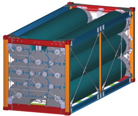
A 20 Feet Container with 500 kg of usable hydrogen with
ADR/ADN-certification is on the market. Currently there are two
pressure levels favoured by the industry: 350 and 500 bar.
500 bar H2 Tank-Tainer with 500 kg of H2.
Source: Argo-Anleg.
For smaller ships needing smaller quantities of H2, a fixed tank
system that can be refueled with a small mobile refueling station might be
a favorable option.
Fuel Purity
When hydrogen is used in the PEMFC,
attention must be paid to hydrogen purity. In principle, any hydrogen
contamination can impair the performance and service life of the fuel
cell system. The required purity is particularly difficult to achieve
during the reforming process from natural gas or methanol. The hydrogen
purity should be above 99.99 Vol.-%. The requested hydrogen for fuel
cell is defined in the Norm EN 17124:2018.
Special Safety & Other Requirements
The primary hazards and issues associated with hydrogen systems can be
categorised and prioritised as follows:
Flammability:
Thermal effects.
Pressure effects.
Easy ignitability of mixtures with oxidant.
Small size of the molecule:
Low viscosity.
High diffusion rate.
High buoyancy.
Interactions with materials (embrittlement of certain metals).
Asphyxiation hazard if oxygen is replaced.
Hazards associated with the storage procedure:
Elevated storage pressure for gas.
Low temperature for cryogenic liquid.
Others for other methods, such as metal hydrides.
ES-TRIN 2023 Article 30.04 states that “a risk
assessment shall be conducted to ensure that risks arising from the use
of fuels with a flashpoint equal to or lower than 55 °C affecting people
on board including passengers, the environment, the structural strength
and the integrity of the craft, are addressed.”
A HAZID study may cover the following areas (as applicable):
General arrangement of vessels.
H2 fuel-storage arrangement and details.
H2 fuel supply and vapour-handling system, from fuel storage
to machinery spaces
H2 fuel arrangement in fuel handling room and engine room
General arrangement of the fuel-handling and engine rooms, including
their ventilation
Main engine safety concepts and vessel integration
Hazardous area classification plans.
Ventilation and vents for stored H2 fuel, fuel-supply system, machinery
space and hydrogen consumer.
H2 fuel-bunkering arrangement.
Safety systems.
Gas detection and firefighting arrangement.
Arrangements to purge or make H2 inert.
Cargo storage and its impact.
Bunkering.
Emergency Escape and Rescue.
Very good forced or natural ventilation of the areas with hydrogen is
necessary. It must also be ensured that EX zones are formed around
installation locations and ventilation outlets.
Crew Skills
As of today, there is no official certificate for training personnel on
the hydrogen. Nonetheless, the crew must be trained and certified to be
able to use the hydrogen system on bord, be familiar with the detection
of leaks and the partial system shutdown procedures. Especially also for
the swapping process of hydrogen tank systems on ships. Currently, the
manufacturer of the hydrogen tank-system must propose a dedicated training
to the crew.
However, CESNI has developed guidelines (recommendations) concerning
competences required for operation of craft using methanol as a fuel and
for operation of craft with an electrical power supply for propulsion.
Similar recommendations are currently being developed for operation of
craft using hydrogen as a fuel.
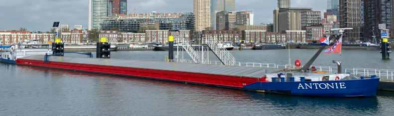
Crew training procedures or H2 Barge 2 and Antonie were composed by the
following chapters:
Familiarity with physical and chemical properties of fuels aboard
ships subject to the ES‑TRIN and IGF Code.
Operate the controls of fuel related to propulsion plant and
engineering systems, services and safety devices on ships subject
to the ES‑TRIN and IGF Code.
Plan and monitor safe bunkering, stowage and securing of the fuel
on board ships subject to the ES‑TRIN and IGF Code.
Take precautions to prevent pollution of the environment from the
release of fuels found on ships subject to the ES‑TRIN and IGF Code.
Monitor and control compliance with legislative requirements.
Take precautions to prevent hazards.
Apply occupational health and safety precautions and measures on
board a ship subject to the ES‑TRIN and IGF Code.
Bunkering & Infrastructure
No bunker
infrastructure for hydrogen is currently available in harbours.
Depending on the size of the future facility, the Directive 2012/18/EU
(Seveso III) specifies requirements: Hydrogen is listed in Annex 1, Part 2
of this Directive, with threshold values of 5 t for "lower‑tier
establishments" and 50 t for "upper‑tier establishments".
Bunkering larger volumes of H2 not only demands standardised
bunkering procedures on the ship, but also demands special regulations to
the port. The bunkering process itself is complex and must be approved for
each individual H2 tank‑system. As there is no
standardisation yet each H2 tank‑system will have its own dedicated
refuelling process. On the shore side, large infrastructure would have
to be installed to bunker H2. It may be that only a certain amount of
hydrogen is permitted to be stored in one place without a special
authorisation procedure. To be able to quickly refill H2 tank‑systems
space for the technical components is needed. These large areas are not
always possible to find in harbours.
Taking away the complexity
of bunkering hydrogen in harbours is an argument for swappable hydrogen
tanks. They could be refilled outside the harbour in a restricted area
or directly at hydrogen production site. This would merely make the
bunkering a logistics task.
For any bunker strategy it
is necessary to check for availability and possible fuelling locations
at the beginning of the project.
Economics
The investment and operating costs are
highly dependent on the individual ship and its operational profile.
Nevertheless, there are key figures for some components. These are
linked to a database so that they are updated as soon as new information
is available.
Investment Costs
Operational Costs
Deployment Examples
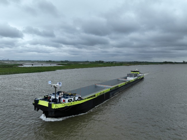
H2 Barge 1
Source: Future Proof Shipping.
Vessel type
Inland container vessel
ENI
02323207
Vessel Size
110.0 m × 11.45 m
Build Year
1997; Retrofit year 2023
Propulsion
PEM Fuel Cell system – three fuel cell units
(3 x 275 ), 800 kW
electric engine, 504 kWh battery
Hydrogen Capacity
2 x 500 kg, in swappable containers
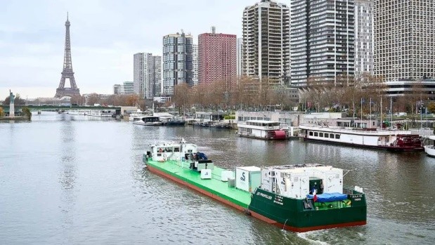
MANNHEIM I+II
Source: Contargo.
Vessel type
Coupled convoy
ENI
04814490
Vessel Size
(105.0 + 88.0) m × 11.45 m
Build Year
Propulsion
2 x 200 kW Ballard FC-Wave, 5 x 390 Euro 6 engine,
840 kWh batteries,2 x 950 kW electric engines
Hydrogen Capacity
up to 4 x 500 kg at 500 bar in swappable containers
The content of the publication herein is the sole responsibility of the publishers and
it does not necessarily represent the views expressed by the European Commission or its
services. While the information contained in the document is believed to be accurate,
the author(s) or any other participant in the SYNERGETICS consortium make no warranty
of any kind with regard to this material including, but not limited to the implied
warranties of merchantability and fitness for a particular purpose. Neither the
SYNERGETICS Consortium nor any of its members, their officers, employees or agents
shall be responsible or liable in negligence or otherwise howsoever in respect of
any inaccuracy or omission herein.